- 您现在的位置:买卖IC网 > Sheet目录368 > UPD44647366AF5-E22-FQ1-A (Renesas Electronics America)SRAM QDRII 72MBIT 165-PBGA
μ PD44647094A-A, 44647184A-A, 44647364A-A, 44647096A-A, 44647186A-A, 44647366A-A
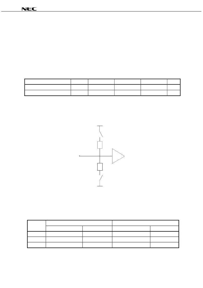
On-Die Termination (ODT)
On-Die Termination (ODT) is enabled by setting ODT control pin to HIGH at power-on sequence. The ODT resistors
(R TT ) are set to 0.6 x RQ, where RQ is a resistor from ZQ pin bump to ground. With ODT on, all the Ds and BW#s are
terminated to V DD Q and V SS with a resistance R TT x 2. The command, address, and clock signals are not terminated.
Figure below shows the equivalent circuit of a Dxx and BWx# receiver with ODT. ODT at the Ds and BW#s are always
on.
When the ODT control pin is LOW or No Connect at power-on sequence, the ODT function is always off.
When the ODT be changed the state after power-on, the AC/DC characteristics cannot be guaranteed.
On-Die Termination DC Parameters
Description
On-Die termination
External matching resistor
Symbol
R TT
RQ
MIN.
105
175
TYP.
150
250
MAX.
210
350
Units
Ω
Ω
Remark
The allowable range of RQ to guarantee impedance matching a tolerance of ± 20 % is between 175 Ω
and 350 Ω .
On- Die Termination-Equivalent Circuit
V DD Q
SW
R TT x 2
Dxx, BWx#
Receiver
R TT x 2
SW
V SS
QDR Consortium specification for ODT is defined when 6R is HIGH and vendor specification when 6R is LOW or
Floating. NEC specification is "Disabled" with 6R LOW or Floating as follows.
ODT-option clarification
6R input
ODT function
Termination value
Consortium specification
NEC specification
Consortium specification
NEC specification
HIGH
LOW
Floating
Active
Vendor specification
Vendor specification
Active
Disabled
Disabled
R TT = 0.6 x RQ
Vendor specification
Vendor specification
R TT = 0.6 x RQ
–
–
10
Note
In case of nominal value (RQ = 250 Ω ), R TT = 150 Ω .
Data Sheet M19962EJ2V0DS
发布紧急采购,3分钟左右您将得到回复。
相关PDF资料
USB-100
KIT STARTER FOR USB
USBMLCF
USB BDM INTERFACE MC P&E
USBMLPPCBDM
MULTILINK P&E POWERPC USB
V-9767-L
DOOR ECONOGLAS 19" LOCKING
VC-9931
CABINT VISNCB 20.54X23.62X23.62"
VC-9934B
VISIONCAB B 35.40X23.62X23.62"
VLA500-01
IC IGBT GATE DVR/DC-DC CONV 12A
VLA502-01
IC IGBT GATE DVR/DC-DC CONV 12A
相关代理商/技术参数
UPD44647366AF5-E25-FQ1
功能描述:SRAM QDRII 72MBIT 165-PBGA RoHS:是 类别:集成电路 (IC) >> 存储器 系列:- 标准包装:3,000 系列:- 格式 - 存储器:EEPROMs - 串行 存储器类型:EEPROM 存储容量:8K (1K x 8) 速度:400kHz 接口:I²C,2 线串口 电源电压:1.7 V ~ 5.5 V 工作温度:-40°C ~ 85°C 封装/外壳:8-SOIC(0.154",3.90mm 宽) 供应商设备封装:8-SOIC 包装:带卷 (TR)
UPD44647366AF5-E25-FQ1-A
功能描述:SRAM QDRII 72MBIT 165-PBGA RoHS:是 类别:集成电路 (IC) >> 存储器 系列:- 标准包装:3,000 系列:- 格式 - 存储器:EEPROMs - 串行 存储器类型:EEPROM 存储容量:8K (1K x 8) 速度:400kHz 接口:I²C,2 线串口 电源电压:1.7 V ~ 5.5 V 工作温度:-40°C ~ 85°C 封装/外壳:8-SOIC(0.154",3.90mm 宽) 供应商设备封装:8-SOIC 包装:带卷 (TR)
UPD446C-2L
制造商:NEC Electronics Corporation 功能描述:2K X 8 STANDARD SRAM, 200 ns, PDIP24
UPD446G-20L
制造商:NEC Electronics Corporation 功能描述:2K X 8 STANDARD SRAM, 200 ns, PDFP24
UPD45128163G5
制造商:Renesas Electronics Corporation 功能描述:128 MBIT SDRAM
UPD45128163G5-A75-9JF
制造商:Elpida Memory Inc 功能描述:8M X 16 SYNCHRONOUS DRAM, 5.4 ns, PDSO54
UPD45128841G5-A75-9JF
制造商:NEC Electronics Corporation 功能描述:SDRAM, 16M x 8, 54 Pin, Plastic, TSOP
UPD4516161AG5A109NF
制造商:NEC Electronics Corporation 功能描述:
